The following Infineon products are supported by this library:
PROFET™ +2 12V family
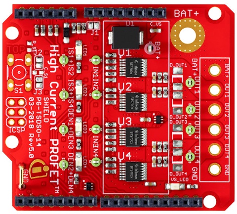
Shields for Arduino
Pinout Diagram
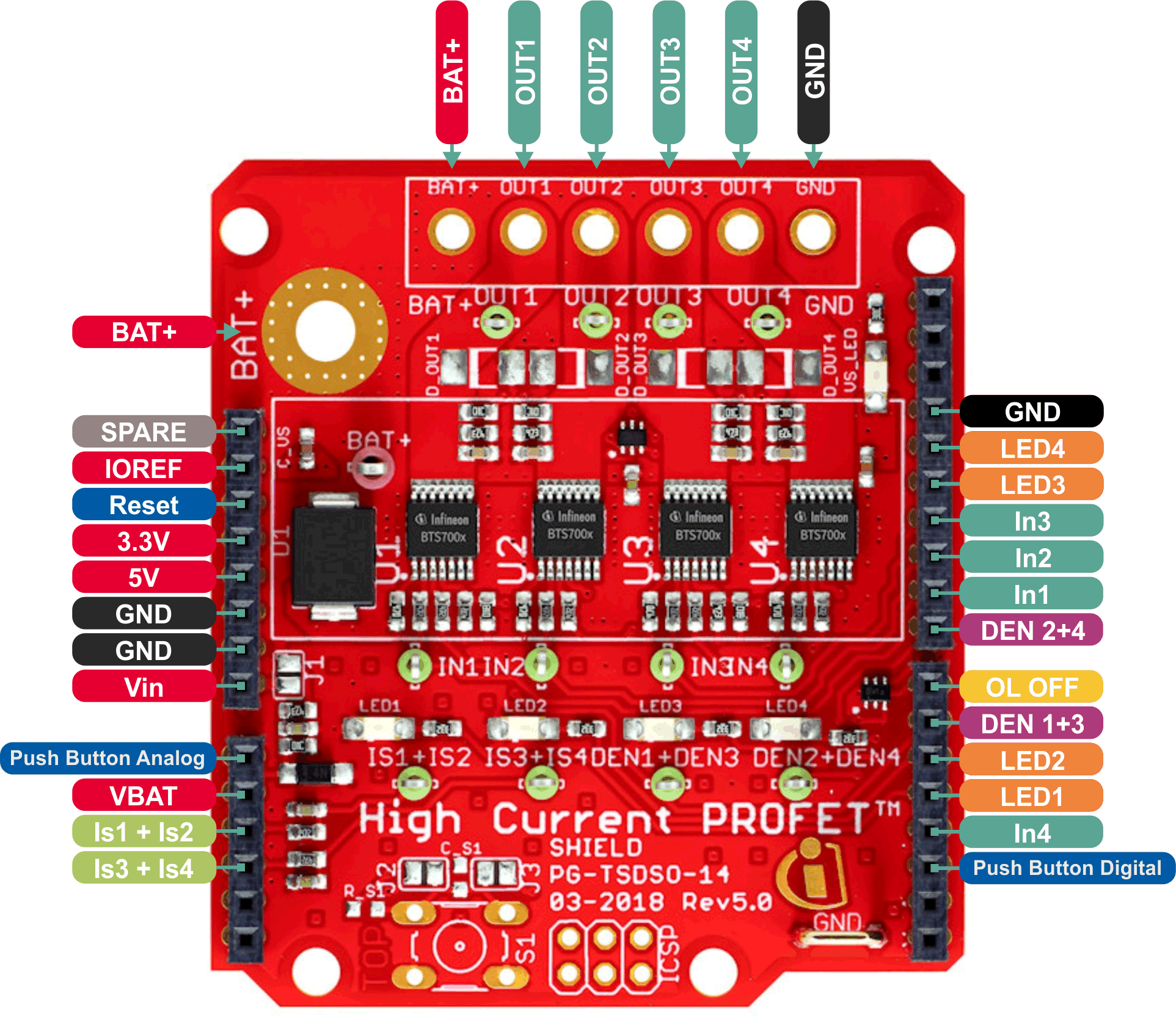
Pin Description
Arduino Pin |
Symbol |
Type |
Function |
|---|---|---|---|
GND |
GND |
- |
Ground |
D2 |
Push button digital |
Output/digital |
Push button digital (optional). |
D3 |
IN4 |
Input/PWM |
Input PROFET™+2 device U4. |
D4 |
LED1 |
Input/PWM |
Indicator LED 1. |
D5 |
LED2 |
Input/PWM |
Indicator LED 2. |
D6 |
DEN 1+3 |
Input/digital |
Diagnosis enable PROFET™+2 device U1+U3. |
D7 |
OLOFF |
Input/digital |
Option for Open Load in OFF detection. |
D8 |
DEN 2+4 |
Input/digital |
Diagnosis enable PROFET™+2 device U2+U4. |
D9 |
IN1 |
Input/PWM |
Input PROFET™+2 device U1. |
D10 |
IN2 |
Input/PWM |
Input PROFET™+2 device U2. |
D11 |
IN3 |
Input/PWM |
Input PROFET™+2 device U3. |
D12 |
LED3 |
Input/PWM |
Indicator LED 3. |
D13 |
LED4 |
Input/PWM |
Indicator LED 4. |
- |
VIN |
- |
Supply voltage. |
A0 |
Push button analog |
Output/analog |
Push button analog (optional). |
A1 |
VBAT |
Output/analog |
Measuring of VBAT via voltage divider. |
A2 |
IS 1+2 |
Output/analog |
Current sense of PROFET™+2 device U1+U2. |
A3 |
IS 3+4 |
Output/analog |
Current sense of PROFET™+2 device U3+U4. |
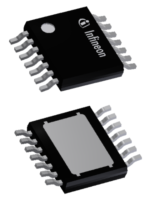
Chip only
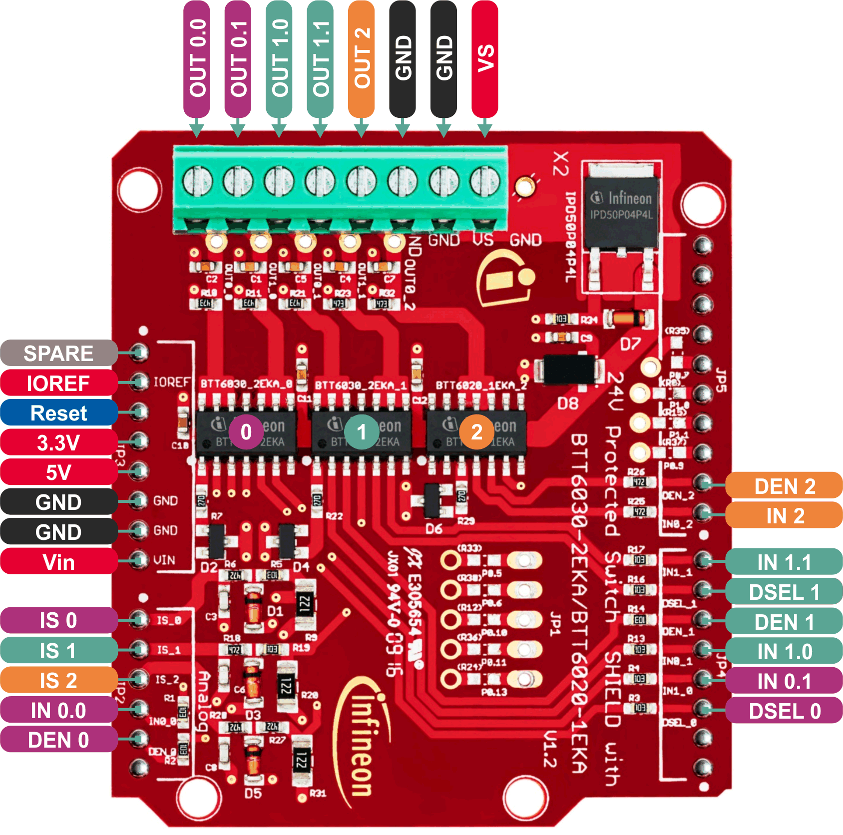
PROFET™ + 24V family
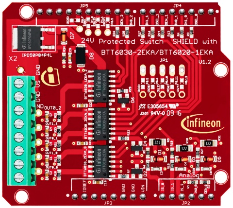
Shields for Arduino
Pinout Diagram
Pin Description
Arduino Pin |
Symbol |
Type |
Function |
|---|---|---|---|
GND |
GND |
- |
Ground |
D2 |
DSEL 0 |
Input/digital |
Diagnostic select PROFET™+ 24V device no. 0. Selects if the diagnosis of channel 0 or 1 is muxed to the IS Pin. |
D3 |
IN 0.1 |
Input/PWM |
Input to switch channel 1 on PROFET™+ 24V device no. 0. |
D4 |
IN 1.0 |
Input/PWM |
Input to switch channel 0 on PROFET™+ 24V device no. 1. |
D5 |
DEN 1 |
Input/digital |
Turns diagnosis for PROFET™+ 24V device no. 1 on or off. |
D6 |
DSEL 1 |
Input/digital |
Diagnostic select PROFET™+ 24V device no. 1. Selects if the diagnosis of channel 0 or 1 is muxed to the IS Pin. |
D7 |
IN 1.1 |
Input/PWM |
Input to switch channel 1 on PROFET™+ 24V device no. 1. |
D8 |
IN 2 |
Input/PWM |
Input to switch channel on PROFET™+ 24V device no. 2. |
D9 |
DEN 2 |
Input/digital |
Turns diagnosis for PROFET™+ 24V device no. 2 on or off. |
A0 |
IS 0 |
Output/analog |
Current sense of PROFET™+ 24V device no. 0 |
A1 |
IS 1 |
Output/analog |
Current sense of PROFET™+ 24V device no. 1 |
A2 |
IS 2 |
Output/analog |
Current sense of PROFET™+ 24V device no. 2 |
A3 |
IN 0.0 |
Input/PWM |
Input to switch channel 0 on PROFET™+ 24V device no. 0. |
A4 |
DEN 0 |
Input/digital |
Turns diagnosis for PROFET™+ 24V device no. 0 on or off. |
- |
OUT x.y |
- |
Power output of channel y on PROFET™+ 24V device no. x. |
- |
Vs |
- |
Supply input |
Chip only
Power PROFET™ family
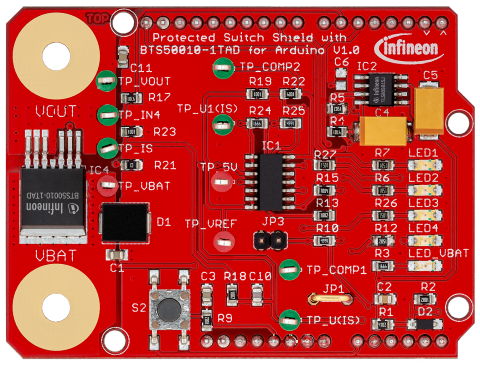
Shields for Arduino
Pinout Diagram
Pin Description
Arduino Pin |
Symbol |
Type |
Function |
|---|---|---|---|
GND |
GND |
- |
Ground |
D5 |
TP COMP 1 |
Output/digital |
Input to check state of comparator 1, can be measured at test point TP_COMP1. |
D6 |
IN - BTS500xx |
Input/PWM |
Input of BTS500xx chip to switch on / off. |
D9 |
LED2 |
Input/PWM |
Input to shield LED no. 2. |
D19 |
LED1 |
Input/PWM |
Input to shield LED no. 1. |
A0 |
S2 |
Output/digital |
Handling of user input. External Key can be connected, low active. |
A2 |
IS |
Output/analog |
Measuring of current IS. |
A3 |
TP 5V |
Output/analog |
Measuring availability of 5V. |
A5 |
VBAT |
Output/analog |
Measuring of VBAT via voltage divider. |
Chip only
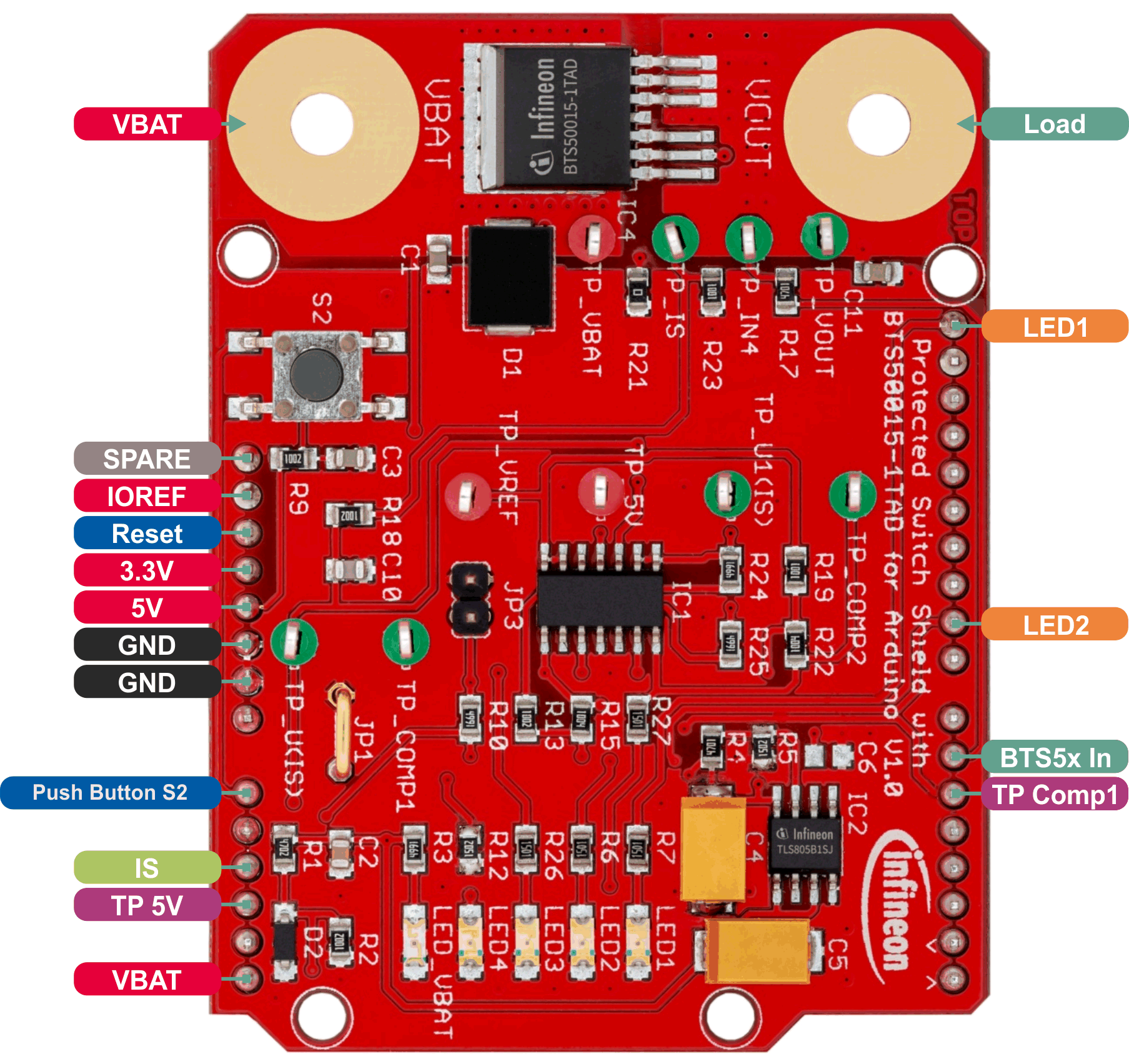
Power PROFET™ + 12V family

Shields for Arduino
Pinout Diagram
Pin Description
Arduino Pin |
Symbol |
Type |
Function |
|---|---|---|---|
D9 |
DEN2 |
Input/PWM |
Diagnosis enable pin for switch 2 |
D10 |
IN2 |
Input/PWM |
Enable pin for switch 2 |
D11 |
DEN1 |
Input/PWM |
Diagnosis enable pin for switch 1 |
D12 |
IN1 |
Input/digital |
Enable pin for switch 1 |
A0 |
IS1 |
Output/analog |
Analog measurement of the current through switch 1 |
A1 |
VS_M |
Output/analog |
Analog measurement of the supply voltage |
A2 |
TEMP_M |
Output/analog |
Analog measurement of the PCB temperature |
A3 |
VOUT_M |
Output/analog |
Analog measurement of the output voltage of switch 1 |
A4 |
IS2 |
Output/analog |
Analog measurement of the current through switch 2 |
Chip only
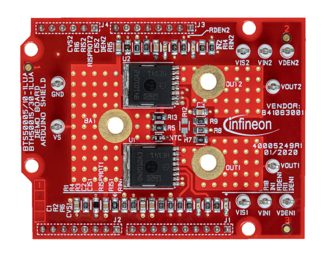
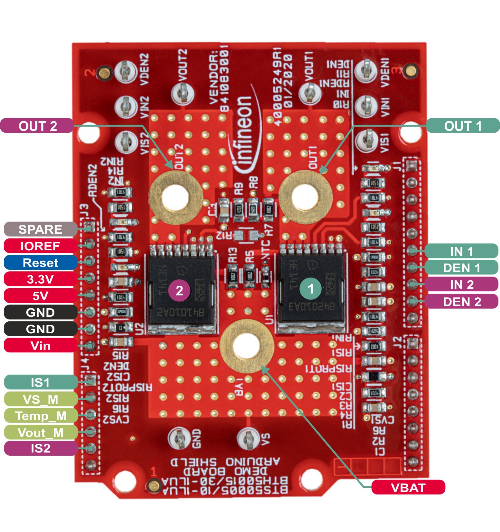
Power PROFET™ + 24V/48V family
Shields for Arduino
Pinout Diagram
Pin Description
Arduino Pin |
Symbol |
Type |
Function |
|---|---|---|---|
D9 |
DEN2 |
Input/PWM |
Diagnosis enable pin for switch 2 |
D10 |
IN2 |
Input/PWM |
Enable pin for switch 2 |
D11 |
DEN1 |
Input/PWM |
Diagnosis enable pin for switch 1 |
D12 |
IN1 |
Input/digital |
Enable pin for switch 1 |
A0 |
IS1 |
Output/analog |
Analog measurement of the current through switch 1 |
A1 |
VS_M |
Output/analog |
Analog measurement of the supply voltage |
A2 |
TEMP_M |
Output/analog |
Analog measurement of the PCB temperature |
A3 |
VOUT_M |
Output/analog |
Analog measurement of the output voltage of switch 1 |
A4 |
IS2 |
Output/analog |
Analog measurement of the current through switch 2 |